Working with equipment of any type eventually requires that you become a mechanic or hire one. Since we're promoting a DIY-ethic, let's get in there and fix it ourselves.
Everybody hurts and everything breaks sometimes
After about 600 hours of printing on the Prusa MK2, the print cooling fan began to fail intermittently causing "drooped" prints where areas with an overhang would began to slough due to inadequate cooling. The support team at Prusa3D asked me to take a video of the printer self-test procedure and after they saw that the fan was not working, they dropped a new fan in the mail and I received it about a week later, having successfully made its trip from the Czech Republic.
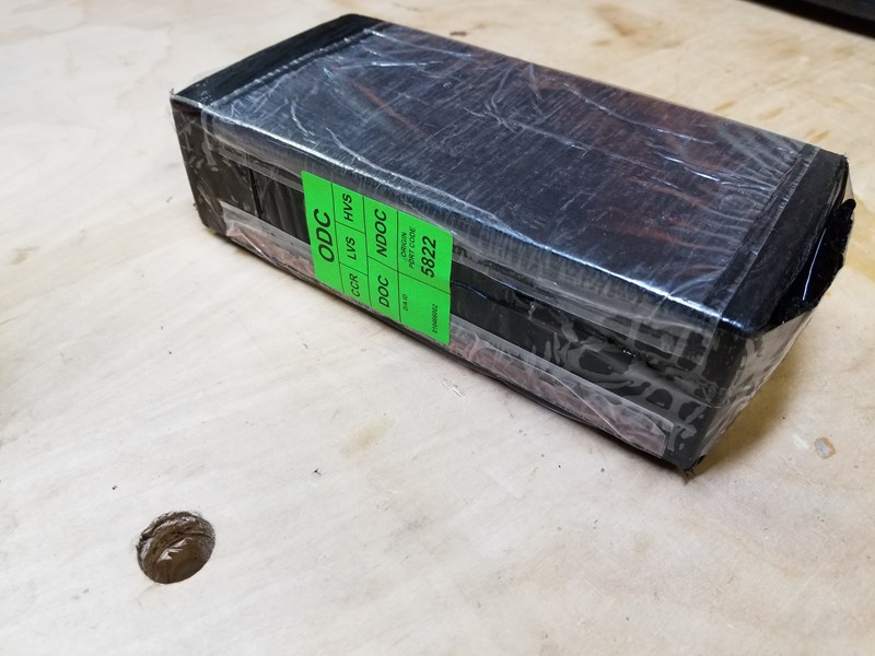
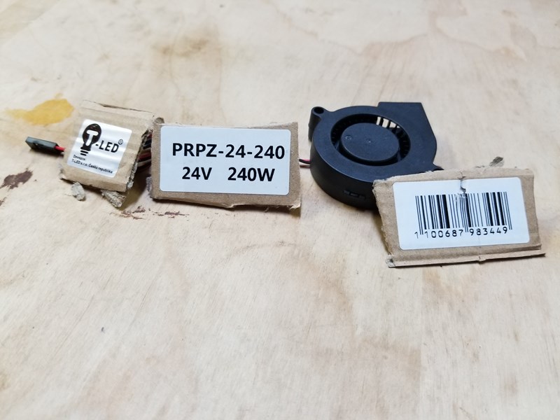
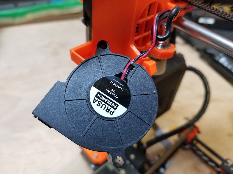
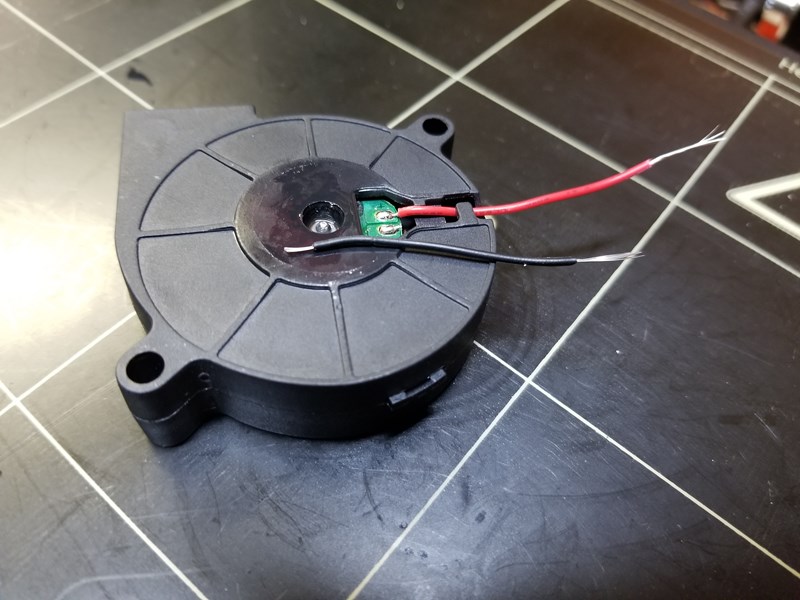
I took some documentation photos of the fan so that I could locate it again if I needed to find another replacement after the warranty period expired. Unfortunately, they sent the fan in a power supply box and so these numbers are meaningless unless you are looking for the power supply used on the Prusa MK2.
Let's get started
The knowledge that I gained by building the MK2 kit paid off. I was still cautious and took the time to think through the best way to accomplish the fan replacement but my confidence level was fairly high.
The first step was to find the proper size replacement zip ties since that is how the cabling for the printer is held in place. It would be a good idea for Prusa3D to include maybe 10 zip ties with a fan replacement since replacing it requires cutting and removing many of the existing zip ties. In any case, I was eventually able to track down replacements that were very close in size and then I started to excavate the fan cabling from the harness.
Taking the easier path
After examining the routing of the fan cable, I changed my mind and decided to avoid extracting the fan cable. There are quite a few cables routed back through this space, so I thought I would take a short cut.
Instead I decided to cut the cables after they emerged from the harness and solder the new fan in place, rather than run the new fan cable all the way back to the Rambo controller unit.
Spoiler! This ended up not working. I tried to take a shortcut and it didn't pan out but let's work through the process anyway. Often people leave out this type of failure in their reporting but in the process of troubleshooting, it is extremely important to know what didn't work and more importantly, why it didn't work.
I detached the fan.
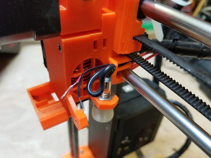
I cut the existing fan leads where I could easily add a solder junction.
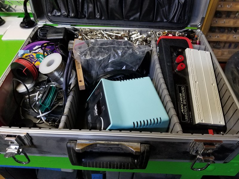
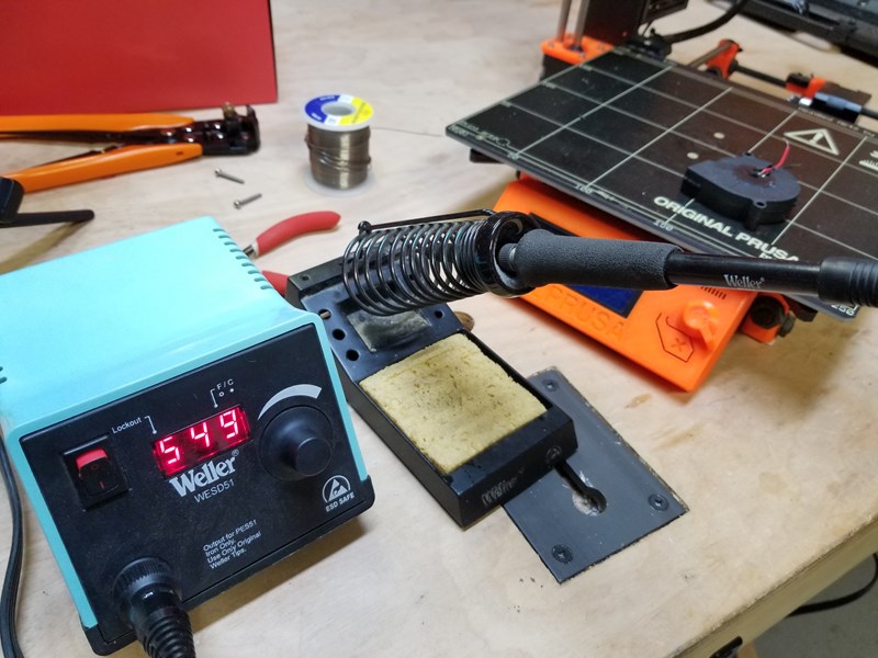
It's always a good day when you get to solder something, to keep the skill fresh. I pulled the Weller digital iron from the tool library and fired it up.
I'm always experimenting with the temperature but I've found that starting at 590F / 310C works fairly well for this type of work. Make sure to tin the tip of the iron with a little bit of solder to help with heat conductivity.
Not pictured, the door to the shop is open and a fan is pulling air to the outdoors. Remember, humans are good at breathing in toxic particulate so proper ventilation is a good thing.
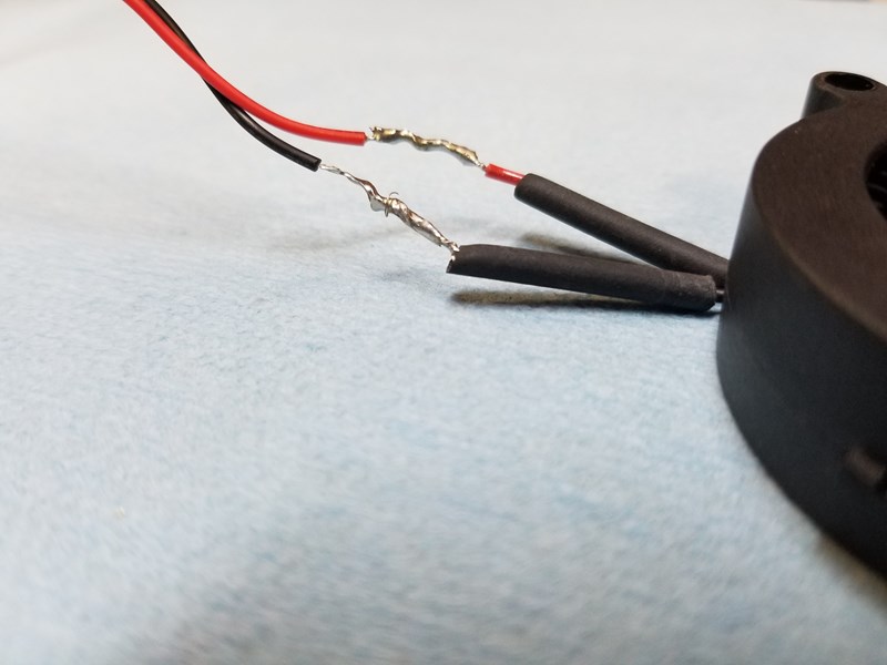
I began preparing the replacement fan by stripping the wires but accidentally pulled to hard and ended up breaking one of the solder joints on the fan, so I soldered new leads onto the fan and twisted the wires together and ran the printer self-test again.
Unfortunately, this did not fix the problem.
When the easy path makes the harder path a tiny bit harder
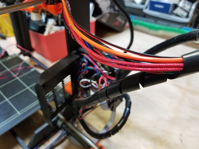
I decided that I needed to trace the issue so I started to remove the existing zip ties in order to excavate the fan wires all the way back to the motherboard.
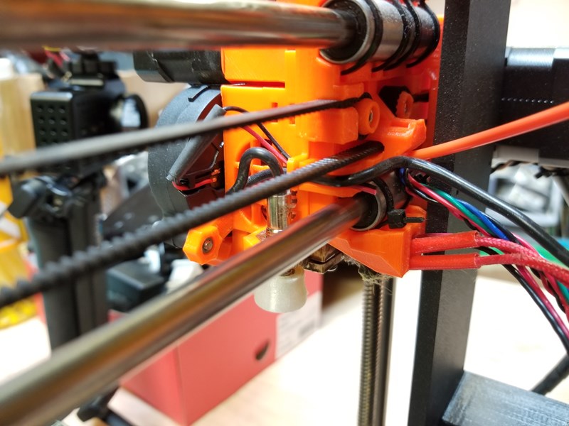
I then removed the zip ties holding the wire harness to the print head.
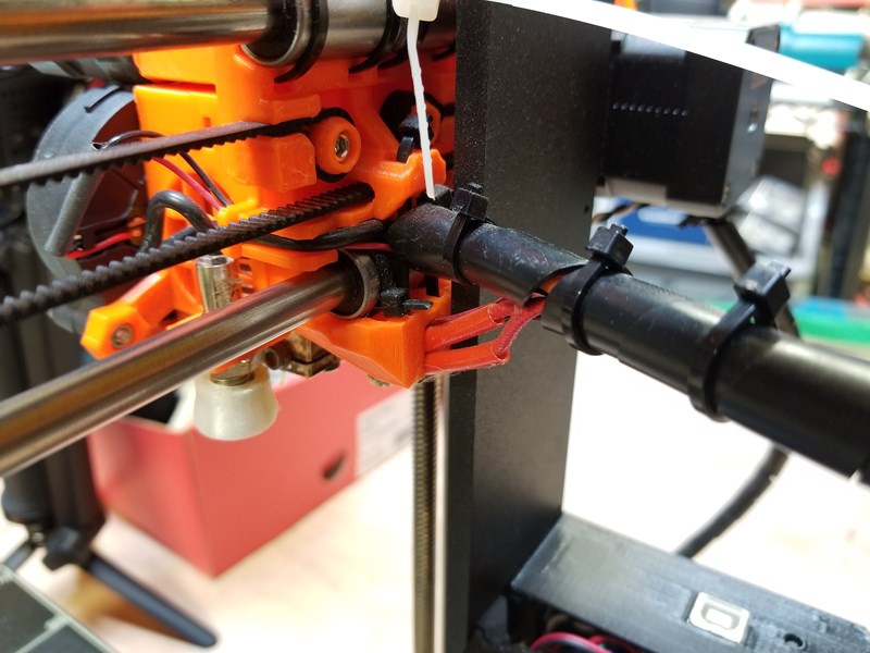
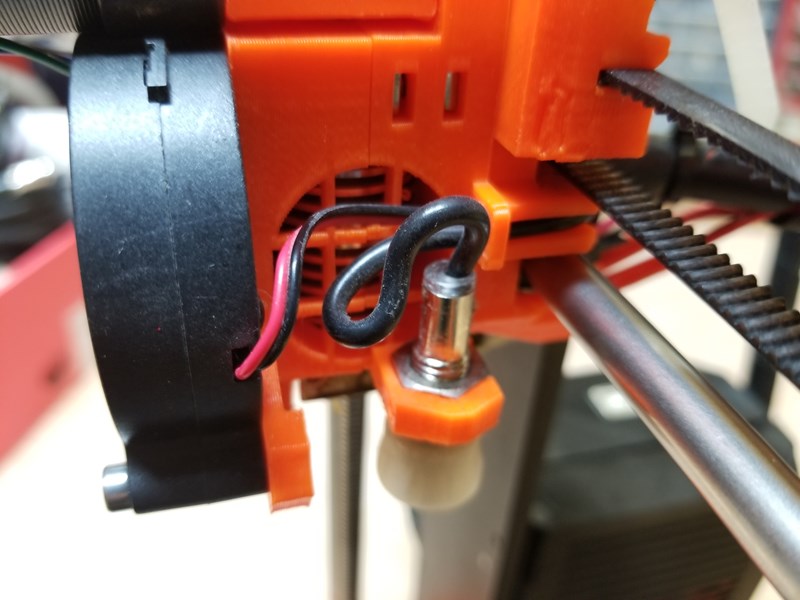
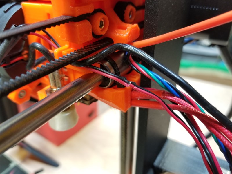
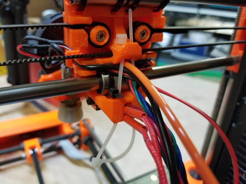
As I extracted the wires, it became obvious what the underlying issue was. The 45 degree angle of the fan wires as they wrapped around the print head to enter the harness had exerted a pinching action on the wires.
This also explains why the issues with the print fan were intermittent.
At different printer head positions, the harness exerted force from a variety of directions. With the additional pinching from the zip ties, the wire was fatally damaged.
The next step upon discovering this issue is to replace the wire for the fan all the way to its termination point.
This involved removing all of the cable wrap.
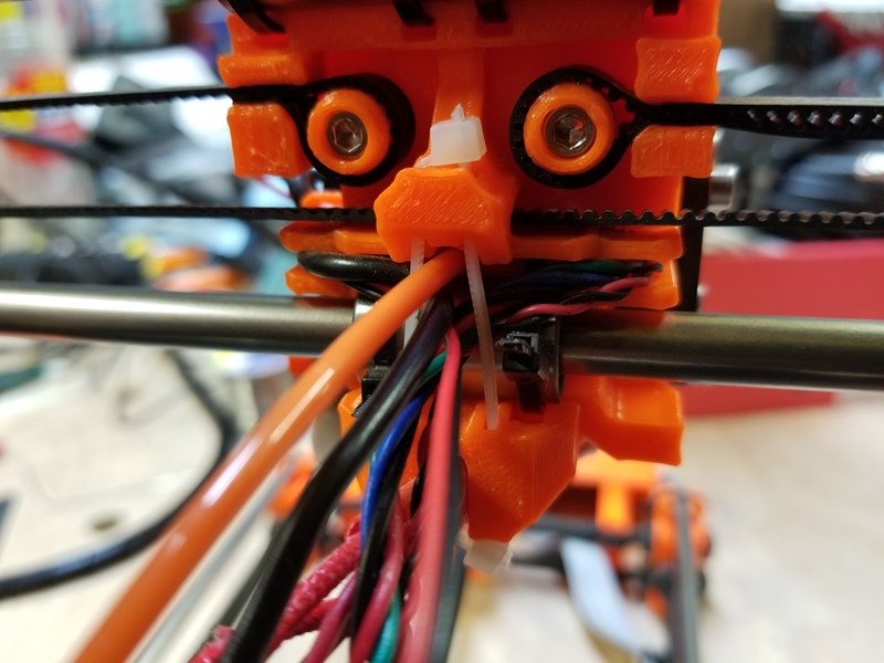
Routing in the new fan wire and replacing the zip tie that keeps the bundle neat and tidy while pondering the anthropomorphism of the back of the print head. I had to double-up the zip tie for length since I didn't have any as long as the original ties.
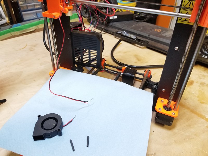
Now that I have the new wire routed and fixed loosely into the harness, it's time to solder on the new fan and make sure it works with the new cable. I threw down a thick shop towel to protect the bed surface of the printer and made the welds.
Always remember to put your heat shrink tubing on the wires BEFORE you solder them together. It's much more difficult if you do it in the wrong order.
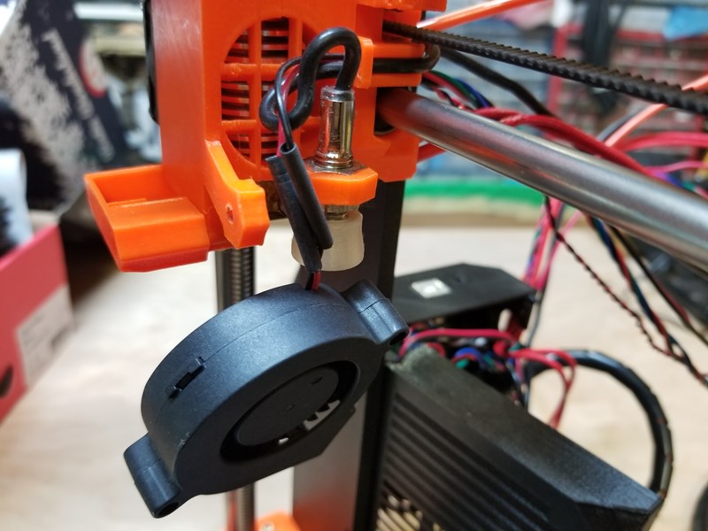
I then installed then new fan and used the soldering iron to set the shrink tubing in place.
It is important to capture all the wires going into the harness between this primary zip tie.
Then I added a couple zip ties to lock the cable wrap in place
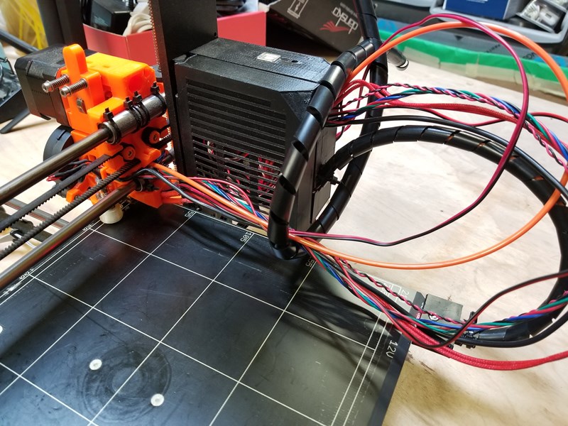
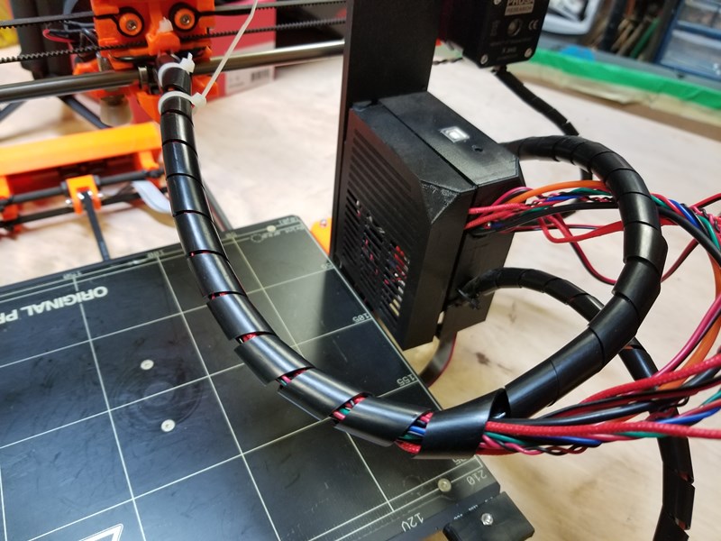
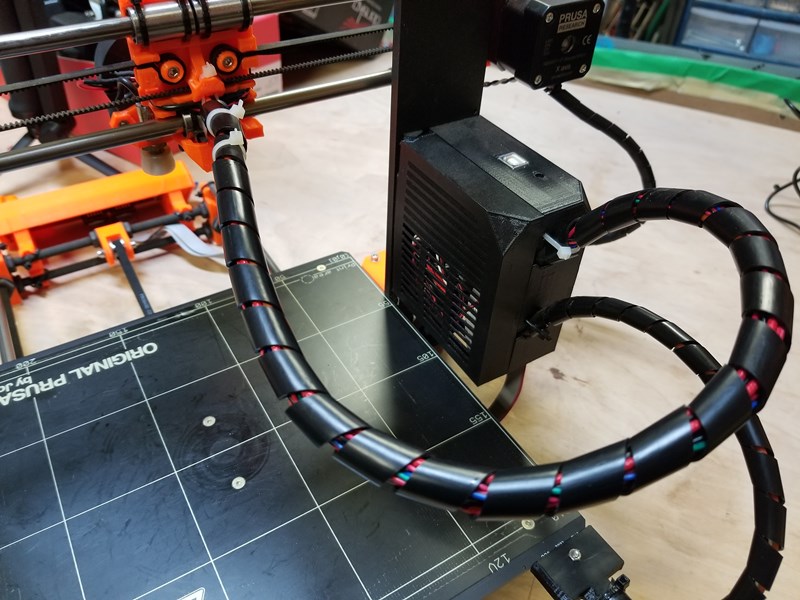
And continue wrapping the bundle all the way back to the Rambo housing.
I ran the self-test and everything checks out.
Ready to print again!
